
Table of Contents
The problem: power budget shortfalls at the edge
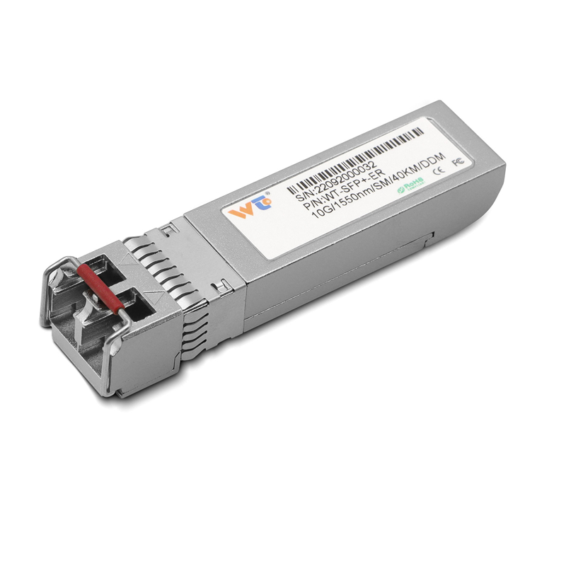
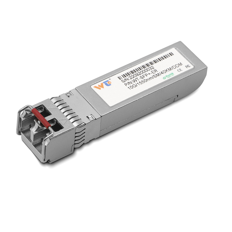
Outdoor distributed networks often fail not because of radio range or cabling, but because PoE power budgets run dry when multiple devices boot under load. Financial trading racks in London’s Docklands and busy transport hubs demand both throughput and reliable power; operators there favour 10G links and SFP+ optics to keep latency down. Early in a deployment, fit a proper module—such as a 10g sfp+ transceiver—and you’ll avoid surprises. The core problem is predictable: a central power supply feeding several powered devices (PDs) via an 8‑port industrial PoE switch will hit thermal and current limits unless the layout and power budget are designed from the start.
Why an 8‑port industrial PoE layout changes outcomes
Compact industrial 8‑port PoE switches give control at the micro-distribution level. With local power sourcing equipment (PSE) close to the PDs, voltage drop is reduced, cable runs shorten, and heat is contained within rugged enclosures. Designers can segment loads: one switch for cameras, another for access points, each with its own power headroom. This also helps when integrating high-speed uplinks—SFP+ modules and 10G infrastructure—without overloading a single chassis. The net effect is fewer field visits and steadier uptime.

Practical layouts and component choices
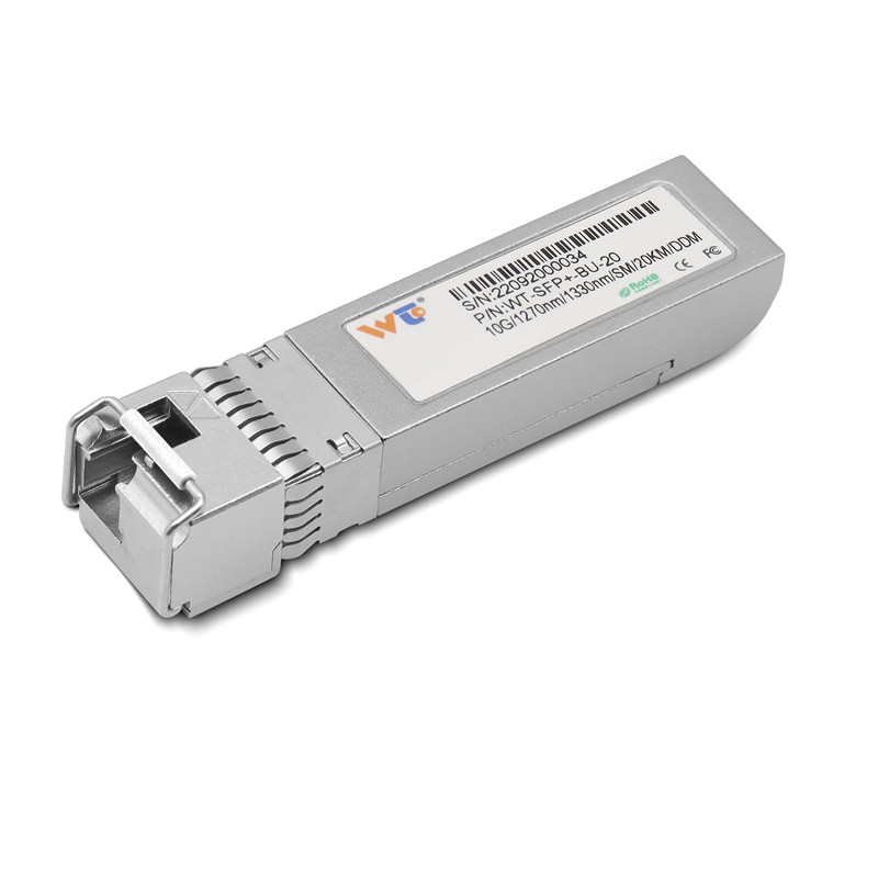
Start by mapping the actual power draw of every PD at boot and steady state. Allow 20–30% headroom for initial inrush and firmware updates. Use local DC distribution or midspan injectors where longer cable runs threaten voltage drop; keep PoE pair length and gauge consistent. Choose switches with per-port power monitoring and configurable limits so you can prioritise critical PDs. Include at least one 10G uplink via SFP+ to aggregate traffic—opt for heat-tolerant transceivers rated for the intended temperature range. Properly selected components prevent a single fault from cascading across the network.
Common mistakes and deployment checklist
Teams often trust nominal port power without validating real wiring conditions. They underestimate inrush current and omit temperature derating. They forget that outdoor enclosures can trap heat, forcing the PSE to throttle. Avoid these errors with a short checklist:
– Measure actual PD draw at boot and runtime, not just datasheet numbers.
– Calculate worst-case cable loss and verify connector integrity.
– Specify per-port current limits and configure automated shutdown for non-critical ports.
– Fit surge protection and a small local battery or UPS to ride through brief outages.
During commissioning, run both data and PoE stress tests. Lab trials should include {main_keyword} and {variation_keyword} scenarios so field behaviour matches assumptions.
Real-world anchor and troubleshooting lessons
In a municipal outdoor Wi‑Fi rollout near a major UK transport hub, teams found that a single overloaded switch caused coordinated reboots across a block of cameras. After redesigning the layout into two 8‑port industrial PoE islands and adding 10G aggregation links using industrial transceivers, outages fell sharply. The lesson: segment power and traffic, and use per-port telemetry to spot creeping faults. Mid-deploy, a mis-specified module—one not rated for the ambient temperature—was the root cause; replacing it with a proper SFP+ part cured recurrent link flaps.
Advisory: three golden rules for selection
1) Power headroom metric — choose switches with at least 30% spare PoE budget under peak boot conditions and verify thermal derating curves.
2) Per-port observability — require real-time current and voltage telemetry; this exposes failing cables or PDs before they cascade.
3) Uplink resilience — mandate at least one 10G SFP+ uplink per aggregation node and use industrial-grade transceivers suited to outdoor temperatures.
Summing up: plan for worst-case boot currents, segment power where possible, and insist on per-port monitoring to keep field visits to a minimum.
— small note: validate spare capacity regularly.
